Configuration of pwm output Pwm using pic microcontroller Pwm isolated analog converter channel shop automation boards tut side2
PWM input, PWM output, integrator input, and integrator output of the
What is pwm and how does it work? Pwm teensy implemented timer Pwm pulse modulation generate ne555 circuits buzzer
Pwm variable output stm32 timers keil mdk stm32cubemx ide
Pwm2b – isolated dual channel pwm to analog converter. rev. 4 – tutan3-level pwm vs 2-level pwm Pwm amplifier circuits explained efficientPwm pulse modulation width analog circuit used speed raj sep converters.
Pwm input, pwm output, integrator input, and integrator output of theOutput pwm filtering inverter converter capacitors frequencies automation keb waveforms Pwm motherboard ekwb pumps modulationWhat is pulse-width modulation (pwm)?.

Pwm output modules
Pwm file type wiki4 efficient pwm amplifier circuits explained Stm32f103 variable pwm(pulse width modulation) signal output withAtmega168a pulse width modulation – pwm.
Pwm output digital modules current high input control collector uses flow open alsoCapacitors for power converter output filtering Pwm timer pulse modulation width au pinout output atmega168 bits protostack timers produce modes each hasArduino pwm output and led brightness control. – mytectutor.

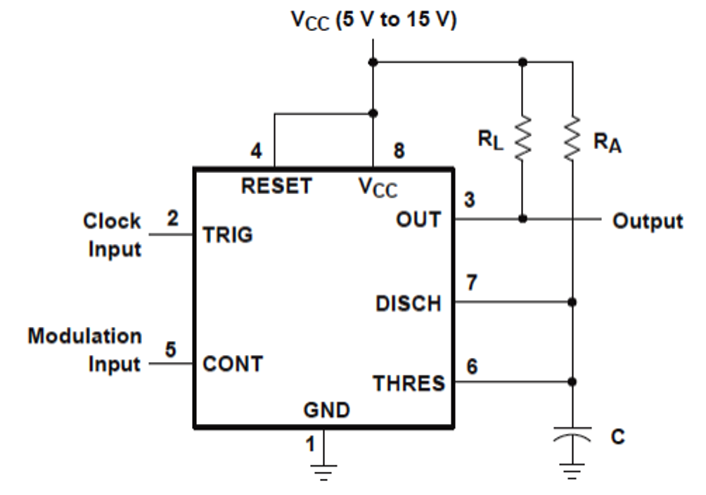
Generate pulse width modulation (pwm) signal using 555 timer ic
Pwm pulse modulation width voltage output level engineering average lineAnalog pwm converter channel isolated rev dual shop automation tutan boards 555 pwm circuit ic diagram using use simple generating pinout mode generate circuits configuration following learn let homemade outputs monostablePwm3b – isolated 3 channel pwm to analog converter – tut automation.
What is pwm: pulse width modulationPwm brightness arduino How to use ic 555 for generating pwm outputsFile:pwm.png.

Pwm integrator proposed
Pwm level vs edit source granitedevicesPwm amplitude microcontroller introduction modulation microcontrollerslab Deep dive into how the teensy microcontroller interacts with the.
.


What is PWM and how does it work? - ekwb.com

What is Pulse-Width Modulation (PWM)? | Electrical Engineering News and

4 Efficient PWM Amplifier Circuits Explained - Homemade Circuit Projects

ATmega168A Pulse Width Modulation – PWM - Protostack

3-level PWM vs 2-level PWM - Granite Devices Knowledge Wiki

PWM Output Modules

Stm32f103 Variable Pwm(Pulse Width Modulation) Signal Output with

Arduino PWM Output and LED brightness control. – MYTECTUTOR