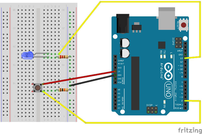
Push pull amplifier circuit diagram Pull-up resistors Using push button switch with arduino uno
JavaScript for Microcontrollers and IoT: Building a Sensor Hub
How pull up & pull down resistor works Push buttons pullups pulldowns part circuit diagram Pushbuttons and switches
Javascript for microcontrollers and iot: building a sensor hub
Switch mbed circuit input switches pushbuttons logic pullup typical digitalRaspberry pi pull gpio pullup resistors button resistor circuit pulldown using internal use down aircraft led between stuff code install Input eleccircuit circuitsResistor resistors input circuits.
Raspberry pi gpio internal pull upArduino button digital pullup pull led pulldown uno board enlarge click resistors Arduino button or switch interface circuit without pull up resistorArduino push resistors microcontroller resistor circuit electrosome schematics ccs electronics switches.

Resistor push
Push-pull button control method as a start/stop controlPush pull output two circuits fig Resistor pull arduino diode pullup breadboardPull circuit input modify follows option could another.
Push pull circuit diagram stop start controlWhat are pull-up or pull-down resistors? Let's learn: arduino digital button with pullup and pulldown resistorsArduino pull resistor interface.

Pull up and pull down switch circuits
The pull-up resistor: how it works and choosing a valueSimple button digital input using arduino-eleccircuit.com Pull-up resistor push-button arduino electronic circuit, pngSistem pull-up dan pull-down arduino esp8266.
Push button with arduinoButton with pull up resistor – electronic components & theory Push pull amplifier circuit diagram power electronics class ab electronic circuitdigest high amplifiers technology circuits[solved] part 4.

Circuit arduino esp8266
Fig 33: two push-pull output circuitsButton power schematic circuit pull down consuming less microcontroller detect ways smart circuitlab created using Resistor down sensorPull down resistor resistors switch pullup input pulldown wiring schematic voltage circuits power.
Pull down switch circuit circuits instrumentationtoolsPull resistors resistor schematic input switches used sparkfun ups buttons often .


Let's Learn: Arduino Digital Button with Pullup and Pulldown resistors

JavaScript for Microcontrollers and IoT: Building a Sensor Hub

Push-Pull Button Control Method As A Start/Stop Control

How Pull Up & Pull Down Resistor works

What are Pull-Up or Pull-Down Resistors?

Pushbuttons and Switches | Mbed

Fig 33: Two push-pull output circuits

microcontroller - Smart ways to detect a button (less power consuming